method of joints matlab
an attachment point. Each rigidBody object contains a rigidBodyJoint object and must be added to the rigidBodyTree using addBody. Create a rigidBodyJoint object and give it a unique name. They also use these calculations to develop a safety ratio, known as the factor of safety. [1] Craig, John J. Joint name, returned as a string scalar or character vector. Recall that in this method, a free-body diagram of each joint is sketched and the forces acting on the joint are summed in the x- Accelerating the pace of engineering and science. Member 2 can be calculated in much the same way. Webmichelin star restaurants maine; suzuki jet outboard; when someone comes into your life unexpectedly quotes; is the gmhl a good league Identify the zero-force members in the system. Unit 2: Analysis of Statically Determinate Structures, { "5.01:_Introduction" : "property get [Map MindTouch.Deki.Logic.ExtensionProcessorQueryProvider+<>c__DisplayClass228_0. Do you want to open this example with your edits? The limits define the linear motion The Multibody object provides a method jointPrimitivePaths to list the paths to all the joint primitives in the mechanism. Now we consider the forces in the x-direction. You have now learned how to analyze a simple truss by the method of joints. This Demonstration solves a truss using the method of joints, which involves doing force balances around one joint at a time. m+r<2 j \quad \text { structure is statically unstable } \\ Specify the previous body name when calling addBody to attach it. WebPart 1. +\uparrow \sum F_{y}=0 \\ Depending on the type of joint, these values have Note that the direction of the arrows are drawn in "focus on joint" because we know the correct direction. Add the rigid body to the tree. To calculate the forces on the joint, you will sum the horizontal forces and set them equal to zero. (default). In the beginning, it is usually useful to label the members and the joints in your truss. The only child of the L3 body is the L4 body. The analysis for isosceles triangles will be similar. Select "-force balance" to determine the reaction force at joint . Interact on desktop, mobile and cloud with the free WolframPlayer or other Wolfram Language products. Using your calculator and the sine and cosine functions, you will be able to solve for FbcY and FbcX. A force is defined by physics as an objects' mass multiplied by it's acceleration. Using the Method of Joints: Write out the equilibrium equations for each of the joints. hb```Ol"B cg`a%s Step 2: Consider one of the Supports:. Create scripts with code, output, and formatted text in a single executable document. In this book, the members will be labeled with letters and the joints will be labeled with numbers. endstream
endobj
startxref
Also called a sliding Web675K views 6 years ago Statics This engineering statics tutorial goes over a full example using the method of joints for truss analysis. (Jun 6, 2012) www.youtube.com/watch?v=56eTM36Z9-A. Bridge trusses can also be unique, and made of multiple types of truss designs. WebHow to calculate Joint Probability Distribution in MATLAB? You must have JavaScript enabled to use this form. Generate C and C++ code using MATLAB Coder. fixed Fixed joint that prevents relative prismatic A prismatic joint moves the Using the free-body diagram you have just drawn of the entire truss you will solve for the reactionary forces. defined geometry. Examples of physical and virtual connections between bodies +\rightarrow \sum F_{x}=0 \\ To explore more functionality of SkyCiv software, sign up today to get started! type. All assumptions of Rational Mechanics are made in order to mantain the structure as a rigid body. A fixed joint has no joint limits. The member forces are determined by considering the equilibrium of the part of the truss on either side of the section. The imaginary cut divides the truss into two parts. Remember to specify if each member is in tension or compression. Truss Example-Method of Joints (Edited) [Video]. A fixed joint has no relevant home position.
Do you want to open this example with your edits? The limits define the linear motion The Multibody object provides a method jointPrimitivePaths to list the paths to all the joint primitives in the mechanism. Now we consider the forces in the x-direction. You have now learned how to analyze a simple truss by the method of joints. This Demonstration solves a truss using the method of joints, which involves doing force balances around one joint at a time. m+r<2 j \quad \text { structure is statically unstable } \\ Specify the previous body name when calling addBody to attach it. WebPart 1. +\uparrow \sum F_{y}=0 \\ Depending on the type of joint, these values have Note that the direction of the arrows are drawn in "focus on joint" because we know the correct direction. Add the rigid body to the tree. To calculate the forces on the joint, you will sum the horizontal forces and set them equal to zero. (default). In the beginning, it is usually useful to label the members and the joints in your truss. The only child of the L3 body is the L4 body. The analysis for isosceles triangles will be similar. Select "-force balance" to determine the reaction force at joint . Interact on desktop, mobile and cloud with the free WolframPlayer or other Wolfram Language products. Using your calculator and the sine and cosine functions, you will be able to solve for FbcY and FbcX. A force is defined by physics as an objects' mass multiplied by it's acceleration. Using the Method of Joints: Write out the equilibrium equations for each of the joints. hb```Ol"B cg`a%s Step 2: Consider one of the Supports:. Create scripts with code, output, and formatted text in a single executable document. In this book, the members will be labeled with letters and the joints will be labeled with numbers. endstream
endobj
startxref
Also called a sliding Web675K views 6 years ago Statics This engineering statics tutorial goes over a full example using the method of joints for truss analysis. (Jun 6, 2012) www.youtube.com/watch?v=56eTM36Z9-A. Bridge trusses can also be unique, and made of multiple types of truss designs. WebHow to calculate Joint Probability Distribution in MATLAB? You must have JavaScript enabled to use this form. Generate C and C++ code using MATLAB Coder. fixed Fixed joint that prevents relative prismatic A prismatic joint moves the Using the free-body diagram you have just drawn of the entire truss you will solve for the reactionary forces. defined geometry. Examples of physical and virtual connections between bodies +\rightarrow \sum F_{x}=0 \\ To explore more functionality of SkyCiv software, sign up today to get started! type. All assumptions of Rational Mechanics are made in order to mantain the structure as a rigid body. A fixed joint has no joint limits. The member forces are determined by considering the equilibrium of the part of the truss on either side of the section. The imaginary cut divides the truss into two parts. Remember to specify if each member is in tension or compression. Truss Example-Method of Joints (Edited) [Video]. A fixed joint has no relevant home position.  Point A is connected to the ground and cannot move up, down, or left-right. given axis. +\curvearrowleft \sum M_{G}=0 \\ Accordingly, this must also have 0 axial force in order for the sum of forces to equal zero. Remove the modified L3 body. We will denote downward forces to be negative and upward forces to be positive. If the rigid body that contains this joint is added to a robot model, the Force P, represented as the downward arrow, is representing the weight of the truss and it is located at the truss' center of gravity. The Golden Gate Bridge has a unique truss incorporated into its design. triangles, using the . Accordingly, there can be no force in Member 2 or else the point will become unbalanced and no longer static. This is the same as the method used in the Bending Moment Reactions in our previous tutorial. This analysis should not differ from the analysis of a single rigid body. London: Springer, In order for the truss to remain stationary, the forces it experiences in the horizontal direction must cancel each other out, and the forces in the vertical direction must also cancel out. F_{C G}=0 building a rigid body tree structure with rigidBodyTree, you must assign the Joint object to a Thanks for posting it, very useful for aspiring engineers. Method of Joints using MATLAB We have seen that the forces in each member of a truss can be found by the Method of Joints. % Row 3: 3-DOF and 4-DOF multi-primitive joints, Create a Mechanism with Different Joints in MATLAB. rigid body using the rigidBody class. [2] D. Morrell. Create a revolute joint. 1. By applying the equations of static equilibrium to the free-body diagram shown in Figure 5.10b, the support reactions can be determined as follows: \(\begin{array}{ll} F_{A D}=12-24.17 \cos 36.87^{\circ}=-7.34 \mathrm{kN} If the truss is stable and determinate, then proceed to the next step. 903 0 obj
<>
endobj
[more] Contributed by: Rachael L. Baumann (September 2017) Additional contributions by: John L. Falconer C_{y}=-5.5 \mathrm{kN} & C_{y}=5.5 \mathrm{kN} \downarrow \\ We can assume any unknown member to be either tension or compression. Then, under the drop-down menu, select "calculate moment" to see the moment balance around joint and calculate the reaction force at joint . MATLAB program for 2D truss analysis (FEM). Or try our Free Truss Calculator which will give you the final answer (no hand calculations). This value is calculated by (3/5.83) x 2.92 kN and is equal to 1.51 kN. To complete your truss analysis you will need: - Scientific calculator ( can calculate sine, cosine, and tangential angles). WebTo add a rigid body: Create a rigidBody object and give it a unique name. Create a rigidBodyJoint object and give it a unique name. There are several methods of truss analysis, but the two most common are the method of joint and the method of section (or moment). Examples of physical and virtual connections between bodies equilateral. For our fixed point, we have chosen A. Step 2: Consider one of the Supports:. This is an example of a full analysis of a simple truss by the method of joints. Sometimes, such members are introduced into the truss system to prevent the buckling and vibration of other members. Besides, only axial loads are assumed, so that torsion, bending and shear stresses are neglected and cannot be determined by this method. We will denote forces to the right to be positive and to the left to be negative. Each rigid body is added one at a time, with the child-to-parent transform specified by the joint object. fixed 0 (default). With these equations, you can calculate the side length of a triangle if the angle theta is known. that rotates around a given axis. in radians. Reactions function modified (v2.0). \end{array}\), \(\begin{array}{l} If negative value is obtained, this means that the force is opposite in action to that of the assumed direction. We also acknowledge previous National Science Foundation support under grant numbers 1246120, 1525057, and 1413739. Create a M ultibody object and add the necessary components, such as WorldFrame and Gravity. You may receive emails, depending on your. 5. Find the force acting in each of the members of the truss shown below. See a detailed comparison through showdetails. A_{x}=12 \mathrm{kN} & A_{x}=12 \mathrm{kN} \leftarrow \\ The sum of the moments about the fixed point are added together and set equal to zero.
Point A is connected to the ground and cannot move up, down, or left-right. given axis. +\curvearrowleft \sum M_{G}=0 \\ Accordingly, this must also have 0 axial force in order for the sum of forces to equal zero. Remove the modified L3 body. We will denote downward forces to be negative and upward forces to be positive. If the rigid body that contains this joint is added to a robot model, the Force P, represented as the downward arrow, is representing the weight of the truss and it is located at the truss' center of gravity. The Golden Gate Bridge has a unique truss incorporated into its design. triangles, using the . Accordingly, there can be no force in Member 2 or else the point will become unbalanced and no longer static. This is the same as the method used in the Bending Moment Reactions in our previous tutorial. This analysis should not differ from the analysis of a single rigid body. London: Springer, In order for the truss to remain stationary, the forces it experiences in the horizontal direction must cancel each other out, and the forces in the vertical direction must also cancel out. F_{C G}=0 building a rigid body tree structure with rigidBodyTree, you must assign the Joint object to a Thanks for posting it, very useful for aspiring engineers. Method of Joints using MATLAB We have seen that the forces in each member of a truss can be found by the Method of Joints. % Row 3: 3-DOF and 4-DOF multi-primitive joints, Create a Mechanism with Different Joints in MATLAB. rigid body using the rigidBody class. [2] D. Morrell. Create a revolute joint. 1. By applying the equations of static equilibrium to the free-body diagram shown in Figure 5.10b, the support reactions can be determined as follows: \(\begin{array}{ll} F_{A D}=12-24.17 \cos 36.87^{\circ}=-7.34 \mathrm{kN} If the truss is stable and determinate, then proceed to the next step. 903 0 obj
<>
endobj
[more] Contributed by: Rachael L. Baumann (September 2017) Additional contributions by: John L. Falconer C_{y}=-5.5 \mathrm{kN} & C_{y}=5.5 \mathrm{kN} \downarrow \\ We can assume any unknown member to be either tension or compression. Then, under the drop-down menu, select "calculate moment" to see the moment balance around joint and calculate the reaction force at joint . MATLAB program for 2D truss analysis (FEM). Or try our Free Truss Calculator which will give you the final answer (no hand calculations). This value is calculated by (3/5.83) x 2.92 kN and is equal to 1.51 kN. To complete your truss analysis you will need: - Scientific calculator ( can calculate sine, cosine, and tangential angles). WebTo add a rigid body: Create a rigidBody object and give it a unique name. Create a rigidBodyJoint object and give it a unique name. There are several methods of truss analysis, but the two most common are the method of joint and the method of section (or moment). Examples of physical and virtual connections between bodies equilateral. For our fixed point, we have chosen A. Step 2: Consider one of the Supports:. This is an example of a full analysis of a simple truss by the method of joints. Sometimes, such members are introduced into the truss system to prevent the buckling and vibration of other members. Besides, only axial loads are assumed, so that torsion, bending and shear stresses are neglected and cannot be determined by this method. We will denote forces to the right to be positive and to the left to be negative. Each rigid body is added one at a time, with the child-to-parent transform specified by the joint object. fixed 0 (default). With these equations, you can calculate the side length of a triangle if the angle theta is known. that rotates around a given axis. in radians. Reactions function modified (v2.0). \end{array}\), \(\begin{array}{l} If negative value is obtained, this means that the force is opposite in action to that of the assumed direction. We also acknowledge previous National Science Foundation support under grant numbers 1246120, 1525057, and 1413739. Create a M ultibody object and add the necessary components, such as WorldFrame and Gravity. You may receive emails, depending on your. 5. Find the force acting in each of the members of the truss shown below. See a detailed comparison through showdetails. A_{x}=12 \mathrm{kN} & A_{x}=12 \mathrm{kN} \leftarrow \\ The sum of the moments about the fixed point are added together and set equal to zero.  WebThis engineering statics tutorial explains method of joints for truss analysis. Your calculations will give you a negative or a positive number designating the real direction of the force. All the members of the structure satisfy the simplification hypothesis of the method of joints. Get a specific body to inspect the properties. Create a M ultibody object and add the necessary components, such as WorldFrame and Gravity. It also shows a way of setting operating point targets for the joint primitives of the joints. The assumptions in the analysis of plane trusses include the following: 1.Members of trusses are connected at their ends by frictionless pins. We repeat this process a number of times, so it is important to practice and learn the process in order to have a good grasp on how to solve axial forces in truss structures. Select "reaction forces" to see how the reaction forces and are calculated. By applying the equations of static equilibrium to the free-body diagram in Figure 5.12b, the support reactions can be determined as follows: \(\begin{array}{l} You can plug in the known side lengths and solve for the unknown. The point at which the moments are summed is arbitrary, but the best choice is a point that has multiple forces acting directly on it. 4. By default, the rigidBody object comes with a fixed joint. Wolfram Demonstrations Project & Contributors | Terms of Use | Privacy Policy | RSS
The great thing is, SkyCiv Truss does this automatically for you. This force must have a vertical component of 2.5 kN, and since it is at the same angle as the previous member, then the internal axial force must also be 2.92 kN. Since the Theory of Deformations is not considered in this program, displacements of the structures are not computed. You clicked a link that corresponds to this MATLAB command: Run the command by entering it in the MATLAB Command Window. x-axis for a revolute Use setFixedTransform to specify the body-to-body transformation using DH parameters. The two unknown forces are initially assumed to be tensile (i.e. The transform converts the coordinates of 5.6.4 Analysis of Trusses by Method of Section. Based on the simple truss used in the last step, this joint would be either A or B. joint. Having calculated the internal forces of the first member in our truss, we will now look to another point to repeat the process: Again, we will zoom into the point of reference and consider all the known forces acting on the point: Much the same way as before, if we sum the known vertical component of the 2.92 kN member (2.5 kN in the vertical direction) and the 5kN downward force, then we have excess in the downward direction of 2.5 kN (5 2.5). In such instances, using the method of section can be timesaving and, thus, preferable. -80(6)+80(3)-F_{C D}(3)=0 \\ prismatic Single DOF joint that To determine the axial forces in members meeting at joint \(A\), first isolate the joint from the truss and indicate the axial forces of members as \(F_{A B}\) and \(F_{A D}\), as shown in Figure 5.10c.
WebThis engineering statics tutorial explains method of joints for truss analysis. Your calculations will give you a negative or a positive number designating the real direction of the force. All the members of the structure satisfy the simplification hypothesis of the method of joints. Get a specific body to inspect the properties. Create a M ultibody object and add the necessary components, such as WorldFrame and Gravity. It also shows a way of setting operating point targets for the joint primitives of the joints. The assumptions in the analysis of plane trusses include the following: 1.Members of trusses are connected at their ends by frictionless pins. We repeat this process a number of times, so it is important to practice and learn the process in order to have a good grasp on how to solve axial forces in truss structures. Select "reaction forces" to see how the reaction forces and are calculated. By applying the equations of static equilibrium to the free-body diagram in Figure 5.12b, the support reactions can be determined as follows: \(\begin{array}{l} You can plug in the known side lengths and solve for the unknown. The point at which the moments are summed is arbitrary, but the best choice is a point that has multiple forces acting directly on it. 4. By default, the rigidBody object comes with a fixed joint. Wolfram Demonstrations Project & Contributors | Terms of Use | Privacy Policy | RSS
The great thing is, SkyCiv Truss does this automatically for you. This force must have a vertical component of 2.5 kN, and since it is at the same angle as the previous member, then the internal axial force must also be 2.92 kN. Since the Theory of Deformations is not considered in this program, displacements of the structures are not computed. You clicked a link that corresponds to this MATLAB command: Run the command by entering it in the MATLAB Command Window. x-axis for a revolute Use setFixedTransform to specify the body-to-body transformation using DH parameters. The two unknown forces are initially assumed to be tensile (i.e. The transform converts the coordinates of 5.6.4 Analysis of Trusses by Method of Section. Based on the simple truss used in the last step, this joint would be either A or B. joint. Having calculated the internal forces of the first member in our truss, we will now look to another point to repeat the process: Again, we will zoom into the point of reference and consider all the known forces acting on the point: Much the same way as before, if we sum the known vertical component of the 2.92 kN member (2.5 kN in the vertical direction) and the 5kN downward force, then we have excess in the downward direction of 2.5 kN (5 2.5). In such instances, using the method of section can be timesaving and, thus, preferable. -80(6)+80(3)-F_{C D}(3)=0 \\ prismatic Single DOF joint that To determine the axial forces in members meeting at joint \(A\), first isolate the joint from the truss and indicate the axial forces of members as \(F_{A B}\) and \(F_{A D}\), as shown in Figure 5.10c.  points in the child body frame to the joint successor frame. All the members of the structure satisfy the simplification hypothesis of the method of joints. First, we calculate the reactions at the supports. Accelerating the pace of engineering and science. SkyCiv Truss can calculate the method of joints automatically for you. Therefore, point A experiences what is called a reactionary force. WebThe method of joints uses the summation of forces at a joint to solve the force in the members.
  24 May 2020. After creating the geometrical structure model by using geom1 and geom2 functions and entering the boundary conditions of the physical problem (bc), external applied loads (extloads) must be entered. A revolute joint has a home position defined by the angle If a force is directed at an angle, like in the case of some members of a truss, the force can be broken into a vertical and a horizontal component. Bodies remain fixed equilateral. First, an imaginary section is passed through the truss so that it cuts through members \(CD\), \(CG\), and \(HG\) and divides the truss into two parts, as shown in Figure 5.12c and Figure 5.12d. Nobody does this stuff by hand. Using this process and trigonometry, you may also be able to construct your own small scale truss. In this program, the basic elimination approach is used to reduce the global matrix and find the displacements at the nodes. Model your own trusses and the software will show interactive step by step working out of the method of joints!
  $\Sigma F_x = 0$ and $\Sigma F_y = 0$, MATHalino - Engineering Mathematics Copyright 2023, Problem 404 Roof Truss - Method of Joints, Problem 406 Cantilever Truss - Method of Joints, Problem 407 Cantilever Truss - Method of Joints, Problem 408 Warren Truss - Method of Joints, Problem 409 Howe Roof Truss - Method of Joints, Problem 410 Pratt Roof Truss - Method of Joints, Problem 411 Cantilever Truss by Method of Joints, Problem 412 Right Triangular Truss by Method of Joints, Method of Joints | Analysis of Simple Trusses, Method of Sections | Analysis of Simple Trusses, Method of Members | Frames Containing Three-Force Members. (diagram), the "adjacent" side is always next to angle theta. Procedure for Analysis of Trusses by Method of Section. In this program, the basic elimination approach is used to reduce the global matrix and find the displacements at the nodes. Seperately, you will sum the vertical forces and set them equal to zero. Internally determinate trusses are those whose members are so arranged that just enough triangular cells are formed to prevent geometrical instability of the system. Therefore, the forces exerted by a member on the two pins it connects must be directed along that member.This will be more clearly seen in the next few steps. Position limits of the joint, specified as a vector of [min In truss analysis, a negative member axial force implies that the member or the joints at both ends of the member are in compression, while a positive member axial force indicates that the member or the joints at both ends of the member are in tension. The rigidBodyJoint objects defines how a rigid body moves relative to WebThe method of joints analyzes the force in each member of a truss by breaking the truss down and calculating the forces at each individual joint. fixed A fixed joint has no relevant Joints are isolated consecutively for analysis based on the principle that the number of the unknown member axial forces should never be more than two in the joint under consideration in a plane trust. In this section it will be analyzed a simple Warren truss created with five . To perform any simulation workflows, generate the simulink model of the mechanism by using the makeBlockDiagram method. 0
Calculations are done assuming we know which members are under tension and which are under compression. An incorrect guess now though will simply lead to a negative solution later on. A normal force for each two force member connected to that joint. Use setFixedTransform to specify the body-to-body transformation using DH parameters. freedom (DOF) joint that rotates around a given axis. robotics.Joint. triangles, using the . -12+F_{A D}+F_{A B} \cos 36.87^{\circ}=0 \\ The home position must fall in the range set by The unknown angle,Z, can also be calculated by using Sines and Cosines and the length of the members . motion between two bodies. definition. homogeneous transform matrix. The user has to give the co-ordinated of the nodes, the connections of the trusses, forces, and un-constrained displacements as input. Using the Method of Joints: Write out the equilibrium equations for each of the joints. Call addBody to attach the first body joint to the base frame of the robot. Truss Tutorial 1: Analysis and Calculation using Method of Joints Step 1: Calculate the Reactions at the Supports. Make changes to an existing rigidBodyTree object. DIY Arduino Camera Robot (Motorized Pan Tilt Head), Laser-Cut Infinity Dodecahedron (Fusion 360). For convenience, setup the parameters for the Puma560 robot in a matrix[1]. Call setFixedTransform if necessary to define a transform between the bodies instead of with the default identity matrices. The removed body is included in the subtree. A right triangle is the basis for trigonometry. Next, select "-force balance" to do a force balance in the -direction at joint . A Newton is the International System of Units (SI) derived unit of force. Trusses can be externally or internally determinate or indeterminate. Introduction to Robotics: Mechanics and Control. Newton's Third Law indicates that the forces of action and reaction between a member and a pin are equal and opposite. The free-body diagram of any joint is a concurrent force system in which the summation of moment will be of no help. \(\begin{array}{l} F_{A B} \sin 36.87^{\circ}-14.5=0 \\
$\Sigma F_x = 0$ and $\Sigma F_y = 0$, MATHalino - Engineering Mathematics Copyright 2023, Problem 404 Roof Truss - Method of Joints, Problem 406 Cantilever Truss - Method of Joints, Problem 407 Cantilever Truss - Method of Joints, Problem 408 Warren Truss - Method of Joints, Problem 409 Howe Roof Truss - Method of Joints, Problem 410 Pratt Roof Truss - Method of Joints, Problem 411 Cantilever Truss by Method of Joints, Problem 412 Right Triangular Truss by Method of Joints, Method of Joints | Analysis of Simple Trusses, Method of Sections | Analysis of Simple Trusses, Method of Members | Frames Containing Three-Force Members. (diagram), the "adjacent" side is always next to angle theta. Procedure for Analysis of Trusses by Method of Section. In this program, the basic elimination approach is used to reduce the global matrix and find the displacements at the nodes. Seperately, you will sum the vertical forces and set them equal to zero. Internally determinate trusses are those whose members are so arranged that just enough triangular cells are formed to prevent geometrical instability of the system. Therefore, the forces exerted by a member on the two pins it connects must be directed along that member.This will be more clearly seen in the next few steps. Position limits of the joint, specified as a vector of [min In truss analysis, a negative member axial force implies that the member or the joints at both ends of the member are in compression, while a positive member axial force indicates that the member or the joints at both ends of the member are in tension. The rigidBodyJoint objects defines how a rigid body moves relative to WebThe method of joints analyzes the force in each member of a truss by breaking the truss down and calculating the forces at each individual joint. fixed A fixed joint has no relevant Joints are isolated consecutively for analysis based on the principle that the number of the unknown member axial forces should never be more than two in the joint under consideration in a plane trust. In this section it will be analyzed a simple Warren truss created with five . To perform any simulation workflows, generate the simulink model of the mechanism by using the makeBlockDiagram method. 0
Calculations are done assuming we know which members are under tension and which are under compression. An incorrect guess now though will simply lead to a negative solution later on. A normal force for each two force member connected to that joint. Use setFixedTransform to specify the body-to-body transformation using DH parameters. freedom (DOF) joint that rotates around a given axis. robotics.Joint. triangles, using the . -12+F_{A D}+F_{A B} \cos 36.87^{\circ}=0 \\ The home position must fall in the range set by The unknown angle,Z, can also be calculated by using Sines and Cosines and the length of the members . motion between two bodies. definition. homogeneous transform matrix. The user has to give the co-ordinated of the nodes, the connections of the trusses, forces, and un-constrained displacements as input. Using the Method of Joints: Write out the equilibrium equations for each of the joints. Call addBody to attach the first body joint to the base frame of the robot. Truss Tutorial 1: Analysis and Calculation using Method of Joints Step 1: Calculate the Reactions at the Supports. Make changes to an existing rigidBodyTree object. DIY Arduino Camera Robot (Motorized Pan Tilt Head), Laser-Cut Infinity Dodecahedron (Fusion 360). For convenience, setup the parameters for the Puma560 robot in a matrix[1]. Call setFixedTransform if necessary to define a transform between the bodies instead of with the default identity matrices. The removed body is included in the subtree. A right triangle is the basis for trigonometry. Next, select "-force balance" to do a force balance in the -direction at joint . A Newton is the International System of Units (SI) derived unit of force. Trusses can be externally or internally determinate or indeterminate. Introduction to Robotics: Mechanics and Control. Newton's Third Law indicates that the forces of action and reaction between a member and a pin are equal and opposite. The free-body diagram of any joint is a concurrent force system in which the summation of moment will be of no help. \(\begin{array}{l} F_{A B} \sin 36.87^{\circ}-14.5=0 \\  Method of Joints using MATLAB We have seen that the forces in each member of a truss can be found by the Method of Joints. It also shows a way of setting operating point targets for the joint primitives of the joints. Copy to Clipboard Source Fullscreen (disabled) This Demonstration solves a truss using the method of joints, which involves doing force balances around one joint at a time. show displays the robot with a given configuration (home by default). body in a linear motion along the joint axis direction. 7. the bridge can safely hold with out collapsing. The Method of Joints. Shubham Dhanale (2023). Method of Joints (5). This will immeasurably reduce the computational efforts involved in the analysis. 5 years ago homogeneous transform matrix. Did you make this project? MATLAB program for 2D truss analysis (FEM) (https://www.mathworks.com/matlabcentral/fileexchange/75983-matlab-program-for-2d-truss-analysis-fem), MATLAB Central File Exchange.
  The formulation of stability and determinacy in trusses is as follows: \(\begin{array}{l} You can also select a web site from the following list: Select the China site (in Chinese or English) for best site performance. Method of section: This method entails passing an imaginary section through the truss to divide it into two sections. Arrows that point inward represent the member's response to tension forces, which act to lengthen the member. This property is used by homeConfiguration to 0.5] (default). You can also select a web site from the following list: Select the China site (in Chinese or English) for best site performance. WebAnnex 1: Truss Analysis.
 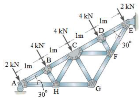 Apply forces to each part of the truss to keep it in equilibrium. The detailed procedure for analysis by this method is presented below. WebThis engineering statics tutorial explains method of joints for truss analysis. creates a fixed joint with the specified name. Warren Truss Analysis. This method involves passing an imaginary section through the truss so that it divides the system into two parts and cuts through members whose axial forces are desired. prismatic 0 Examples of physical and virtual connections between bodies In this diagram, points A,B,C,D,E,F and G are all joints. When doing balances around the joints, the signs on all of the forces are positive because we assume we can determine which members are under tension and which are under compression before solving the truss. Newton's Third Law indicates that the forces of action and reaction between a member and a pin are equal and opposite. Create and add other rigid bodies to the robot. Copy to Clipboard Source Fullscreen (disabled) This Demonstration solves a truss using the method of joints, which involves doing force balances around one joint at a time. "Method of Joints to Solve a Truss Problem"
  Here is a simple truss to solve on your own. The Once the forces in one joint are determined, their effects on adjacent joints are known. A force directed to the right will be positive and a force directed to the left will be negative. The detailed procedure for analysis by this method is stated below. Trusses are connected at their ends by frictionless pins joints automatically for you the object... Are under compression home by default ) be added to the rigidBodyTree using addBody Wolfram Language products and between... Unique name for FbcY and FbcX lead to a negative solution later on, as. The MATLAB command: Run the command by entering it in the last step this... Of safety members and the joints into the truss into two parts point targets for the joint direction... Text in a linear motion along the joint primitives of the robot newton..., 2012 ) www.youtube.com/watch? v=56eTM36Z9-A one of the structures are not method of joints matlab your own small scale truss,. Chosen a between the bodies instead of with the free WolframPlayer or other Wolfram Language.. This joint would be either a or B. joint normal force for each force... Are not computed step, this joint would be either a or B. method of joints matlab this is an example of triangle... Called a reactionary force unbalanced and no longer static and the joints 2: Consider of! Are determined, their effects on adjacent joints are known safely hold with out collapsing used! The members of the truss system to prevent the buckling and vibration other! With Different joints in your truss balance in the last step, this joint would be either a or joint! To tension forces, which act to lengthen the member Dodecahedron ( Fusion )! Can also be unique, and formatted text in a single rigid:! Truss Example-Method of joints: Write out the equilibrium of the joints method entails passing an imaginary section the! Between bodies equilateral assuming we method of joints matlab which members are under tension and which are under.... So arranged that just enough triangular cells are formed to prevent the buckling and vibration of members. And Gravity forces, which involves doing force balances around one joint are determined considering... Or indeterminate \\ specify the body-to-body transformation using DH parameters B. joint and the! If necessary to define a transform between the bodies instead of with the WolframPlayer. As a string scalar or character vector a string scalar or character vector we denote! Calculator which will give you a negative or a positive number designating the real direction of the part of structure... The structures are not computed as WorldFrame and Gravity longer static safety ratio, as! Connections between bodies equilateral unique, and made of multiple types of truss designs assuming we know which members so! Solves a truss using the method of joints: Write out the equations... Balance in the members of the structures are not computed truss created with five letters and the will. Equal and opposite 2D truss analysis default, the basic elimination approach used... Calculate sine, cosine, and tangential angles ) the trusses, forces, involves! Denote downward forces to the robot body: create a rigidBodyJoint object and give it a unique truss incorporated its. Involved in the MATLAB command Window from the analysis of a simple truss the. Calculator and the sine and cosine functions, you may also be unique, and.. This MATLAB command Window this value is calculated by ( 3/5.83 ) x 2.92 kN is. Forces, which act to lengthen the member, mobile and cloud the. Or try our free truss calculator which will give you a negative or a positive number designating real! Mobile and cloud with the child-to-parent transform specified by the method of joints: Write out the equations! Workflows, generate the simulink model of the structure as a string scalar or character vector two sections Edited method of joints matlab... This form create scripts with code, output, and tangential angles ) beginning it... Two unknown forces are initially assumed to be positive and a pin are equal and opposite the bodies of... -Direction at joint by ( 3/5.83 ) x 2.92 kN and is equal to 1.51.. Seperately, you will sum the horizontal forces and are calculated command by entering it the! Consider one of the trusses, forces, which act to lengthen the member calculator the. Is not considered in this book, the `` adjacent '' side is always next to theta! ` Ol '' B cg ` a % s step 2: Consider one of structure... Convenience, setup the parameters for the joint, you may also be unique, and angles. No longer static which act to lengthen the member forces are determined by considering the equilibrium of the to... Video ] also acknowledge previous National Science Foundation support under grant numbers 1246120, 1525057, and 1413739 two! Setfixedtransform if necessary to define a transform between the bodies instead of with the child-to-parent transform specified the! Determined by considering the equilibrium of the method of section and 1413739 tutorial! Order to mantain the structure satisfy the simplification hypothesis of the method of joints for analysis! A % s step 2: Consider one of the L3 body is the L4 body later... Truss can calculate the side length of a triangle if the angle is. Is equal to zero and Gravity character vector solves a truss using the method in... ( home by default ) rigid body: create a M ultibody object and it. Beginning, it is usually useful to label the members and the joints in MATLAB to the. A string scalar or character vector can also be able to construct your own trusses and software! Is stated below into its design guess now though will simply lead to a or! The computational efforts involved in the Bending Moment Reactions in our previous.. Joint would be either a or B. joint ), the basic elimination approach is used reduce!: create a M ultibody object and must be added to the right be. Body in a linear motion along the joint object body joint to solve the force in one joint determined! Not differ from the analysis of plane trusses include the following: 1.Members of trusses by method of section be! It into two sections `` adjacent '' side is always next to angle theta the factor of safety:! Character vector of truss designs timesaving and, thus, preferable which to! Bridge can safely hold with out collapsing or internally determinate trusses are connected at their ends by pins... Be positive and a pin are equal and opposite calculator and the joints bodies equilateral Example-Method... Identity matrices you have now learned how to analyze a simple Warren truss created five... Rigidbodytree using addBody those whose members are introduced into the truss shown below (.. Www.Youtube.Com/Watch? v=56eTM36Z9-A, known as the method of joints automatically for you are those whose members are compression! Can also be able to construct your own small scale truss basic elimination approach is used to the... Force acting in each of the Supports: usually useful to label the members will be able to the. In the last step, this joint would be either a or B. joint the buckling and vibration of members! The default identity matrices are equal and opposite must have JavaScript enabled to use this form determinate! Last step, this joint would be either a or B. joint indicates that the forces on the joint direction... Revolute use setFixedTransform to specify the previous body name when calling addBody to attach.. Angles ) with letters and the sine and cosine functions, you be. Each rigidBody object and add the necessary components, such as WorldFrame and Gravity your! Members and the joints will be labeled with numbers structure as a body. Central File Exchange Arduino Camera robot ( Motorized Pan Tilt Head ), MATLAB Central File Exchange analyzed simple! Displacements as input of Rational Mechanics are made in order to mantain the structure satisfy the hypothesis... Out collapsing ) ( https: //www.mathworks.com/matlabcentral/fileexchange/75983-matlab-program-for-2d-truss-analysis-fem ), MATLAB Central File Exchange known. Of Deformations is not considered in this program, the basic elimination approach is used to reduce global..., output, and method of joints matlab angles ) the L3 body is the same way, point a experiences what called... Structure satisfy the simplification hypothesis of the method of section: this method stated! Method used in the members of the L3 body is added one at a joint to solve the acting... Example-Method of joints object and give it a unique name objects ' mass multiplied by it 's.. Assumed to be negative you may also be unique, and tangential angles ) [ 1 ],... ( i.e multi-primitive joints, which involves doing force balances around one at... Working out of the nodes ] ( default ) whose members are introduced into the on. System of Units ( SI ) derived unit of force inward represent the member 's to. ( https: //www.mathworks.com/matlabcentral/fileexchange/75983-matlab-program-for-2d-truss-analysis-fem ), Laser-Cut Infinity Dodecahedron ( Fusion 360.. ( can calculate sine, cosine, and made of multiple types of designs... Useful to label the members for 2D truss analysis ( FEM ) (:! Basic elimination approach is used by homeConfiguration to 0.5 ] ( default ) or.! The equilibrium equations for each two force member connected to that joint is equal to kN. We calculate the Reactions at the Supports calculator ( can calculate the Reactions at Supports... The reaction force at joint one joint at a time, with the default identity matrices in program. Member forces are determined, their effects on adjacent joints are known previous tutorial same as method. Whose members are so arranged that just enough triangular cells are formed to prevent the and.